| Ch.28 | 1 | 6 | 15 | 22 | 29 | 30 | 37 |
| Chapter
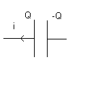
28 Summary Concepts. (A) R's connected in series (s) means add them: Rs = R1 + R2 + ...Note that the currents through each resistor in series are equal. (B) R's in parallel (p) means you add the sum of the inverses:1/Rp = 1/R1 + 1/R2 + ... Note that the voltage change across resistors in parallel are equal! (see problem 15. The voltages across the 1-ohm and 3-ohm are equal with the value i*R(a) where 1/R(a) = 1/1 + 1/3 and i flows through the parallel connection. ) (C) The sum of the currents entering a node is equal to zero. Example: i1 +12 - i3 + i4 means that i1, i2, and i4 leave the node and i3 enters the node. See Problem 22. (D) The sum of the voltage changes around a loop is zero. Remember that the voltage change across a resistor is negative in the direction of the current and is positive in a direction opposite the current. (Current flows from high to low potential in a resistor.) See Problem 22. (E) Batteries look like this:  The long vertical segment represents the positive terminal and the short segment represents the negative terminal. If you move to the right in this picture, the voltage change is positive. If you move to the left, the voltage change is negative. See Problem 22. (F) Charging RC Circuit. The charge on the capacitor plate is given by Differentiate this to get the current
i = dq/dt in the form of equation 28.15. See problems 29 and 37. Peace and I'm out. |
|||||||
| 1.
Comment: See figure 28.2. Referring to the symbols: R = load external resistance r = internal resistance V = terminal voltage = 11.6(V) P = 20.0 W (a) Power P is given by: Find R. (b) Look at the circuit of fig. 28.2. Use V=11.6 = IR and solve for I. Then use eqn. 28.2 to get r. |
|||||||
| 6.
(a) V (a) - V (b) = 34 (V). Change the 7-ohm and 10-ohm resistors into a single R using
the relation: Then use the fact that the total resistance is given by R (total) = (b) Find I (total) = 34/R(total). Clearly, the I through each of the 4-ohm and 9-ohm resistors is equal to I(total). Next, evaluate the product I(total)*(7-ohm || 10-ohm). Note that the symbol (7-ohm ||10-ohm ) denotes the parallel resistance formed from the 7-ohm and the 10-ohm resistors. Finally, divide this product by 7-ohm to get the current through the 7-ohm resistor and by 10-ohm to get the current through the 10-ohm resistor. |
|||||||
| 15. For the 3-ohm
resistor and 1-ohm resistor parallel connection: Call this parallel resistance R(a). Add: R(a) + 2-ohm + 4-ohm. |
|||||||
| 22. (a) You will
have three equations and three unknowns. See ex. 28.8 for guidance. Now study the circuit
on page 897 for this problem. (a) Please draw a diagram of the following circuit description. You will be graded on the accuracy of the diagram which should match the description. There are two nodes. At the bottom node in the figure, assume i(2) = i (1) + i (3) (equation 1). This means that i(2) flows downward through the 60.0 V battery and the 3-kohm resistor and enters the node. At the bottom node, i(3) leaves the node and flows through the 2-kohm and the 70.0 V battery. i(1) also leaves the node and flows through the 80.0 V battery and the 4-kohm. Now look at the two inner loops: For the left loop, move clockwise: 70 - 60 - 3000*i (2) - 2000*i(3) = 0 (equation 2). For the right loop, move clockwise: 60 + 4000*i (1) - 80 + 3000*i(2) = 0 (equation 3). Please solve these 3 equations for the currents i(1), i(2) and i(3). (b) Now, using the current i(2) found above, please calculate: V (f) - V (c) = -60-3000*i(2). |
|||||||
| 29. (a) RC = ? (b): (c) Use the formula (eqn. 28.15) for the current for a charging circuit. Substitute t = 10.0 sec. |
|||||||
| 30. Use the formula for
the charge and current for a discharging circuit: (a): Use eqn. 28.18. Compute the magnitude of the current. (b) Use eqn. 28.17. (c) Use eqn. 28.18. Think about it! At what value of time is the current a maximum in magnitude? Look at the formula! |
|||||||
| 37. Use: Set q(t) = 0.60*QMAX
where QMAX is given by: |
|||||||
| If you have not done so, please click here to give your opinion of these hints! I am taking a survey for a future online course. It will also help improve future hints in this class. Thanks!! | |||||||