Ch.30

36 Ch.31   12 20 29 33
Answers

Ch. 30

Ch. Summary--Sec 30.7. (Summaries for the other sections are in Quiz 12 ):
 There are two types of current that appear in the Ampere-Maxwell law, conduction and displacement current, as discussed in class:

Here, i = conduction current and id = displacement current.
The rules for finding the direction of the magnetic field are the same as before. 

 For example, for a cylindrically symmetric situation, point your right thumb in the direction of either id or i and your right fingers will wrap in the direction of the B-vector .
The displacement is given by:

36.  Please read sec. 30.7 As you can see in Fig. 30.24 and 30.25.  There are two types of current that appear in the Ampere-Maxwell law, conduction and displacement current, as discussed in class:

Here, i = conduction current and id = displacement current.
The rules for finding the direction of the magnetic field are the same as before. For example, for a cylindrically symmetric situation, point your right thumb in the direction of either id or i and your right fingers will wrap in the direction of the B-vector .
The displacement is given by:

This is the product of the permittivity of free space and the rate of change of the electric flux. The flux is given by:

If the electric field varies in time, then the flux also varies in time. For this problem we focus attention on the region between the plates of a capacitor. There, the conduction current i is zero and the displacement current is not zero because the electric field is changing in time as the plates become increasingly charged.
Now, we know that

This was covered in Chapter 26. We evaluate the flux through a circular surface area A (= plate area) that is in the space between the plates and is parallel to the plates.

Thus, the flux is:
,

where q = the charge on the positive plate.
Thus,


Here we have used the fact that the derivative of the charge on the positive plate is equal to the conduction current i.
Thus,


Evaluate this using the numbers given for the plate radius and current i. A = area of the circular plates of radius 0.10 m

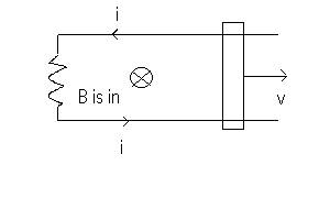
(b) The direction of the magnetic field in the region between the plates can be determined from the right hand rule. Let's take a look at the front view of the system between the plates. Below is shown the inner circle of integration used to find B. Your thumb will point outward in the direction of the displacement current. Thus your fingers and the vector B-field lines are in circular loops that are counter clockwise. The inner circular loop below represents the loop of integration with radius r. Note that r is less than R, the radius of the circular plates shown by the outer circle. These plates have radius R = 0.10 m. The integral on the inner loop is equal to the permeability times the displacement current from Ampere- Maxwell's law. Note that between the plates there is no conduction current , so i = 0. Thus,
.

The electric flux is for an area equal to that of a circle of radius r. This is because the displacement current is enclosed within the circle of radius r.


Thus, the electric flux associated with the displacement current at r = 0.05 m is:

Be careful! Therefore,

But from part (a), the derivative of the magnitude of the electric field is given by:

Substitute this last expression into the equation just above it, and solve for the magnitude B of the magnetic field.

Ch. 31

Ch. Summary:

A.

N = number of loops in the coil. Typically N = 1 for a simple single loop. The 4 basic cases follow:
Case 1: Assume that the external B-vector is out and B-magnitude increases. Thus,  induced current is clockwise  to oppose this change. 


Case 2: Assume that the external B-vector is out and B-magnitude decreases. Thus,  induced current is counterclockwise  to oppose this change. 


Case 3: Assume that the external B-vector is in and B-magnitude increases. Thus,  induced current is counterclockwise  to oppose this change. 


Case 4: Assume that the external B-vector is in and B-magnitude decreases. Thus,  induced current is clockwise  to oppose this change. 


B. For the case of a moving rail system as in Figure 31.9, we have:

The external field B is constant and points in. Since the area of the flux increases as the rail moves right, i is counterclockwise. If the area decreased for  the rail moving left, i would be clockwise.

C. Induced electric fields. Assume that B-vector is in and increases in magnitude. Then the E-vector is counterclockwise to oppose this change. 


12. Assume that the external B-vector is out, as indicated in the figure. The magnitude of this B-vector is:

Now, according to our discussion in class, the induced B-vector acts in the opposite direction to the external B-vector. This is because the external vector-B is increasing in magnitude. Thus, according to the results given by ex. 30.3, page 868, the induced current is clockwise. Therefore, the sense of the induced emf is also clockwise.

Now, the total flux is NBA, where N = 30, B is given by the above formula as a function of time t, and A is the areaof a circle of radius 0.04 m. The magnitude of the emf is given by:

Compute the derivative of B using basic concepts from Math 1,or for that matter, the back of the textbook, Appendix B, A.27.
 

20. Fig. P31.20.  Note that the external magnetic field vector- B points in and has constant magnitude. In those examples, the rail moves to the right. And that increases the effective area of the loop! The net effect is that the flux increases. Qualitatively, this is equivalent to having a loop with fixed area, with a magnetic field vector that points in with magnitude that increases:

Now, we know that if the magnitude of the external B-vector increases for the direction shown in the above figure, then the induced B-vector points out. Thus, by the right-hand-rule for loops, the induced current is counterclockwise. And in the figures in the book, including fig. P31.20, the current therefore is counterclockwise. (i.e. flows downward through the resistors shown in those figures.)

Having said all that, we now turn to the specific problem at hand: Find

Divide this by R to get i. Solve for speed v if i = 0.500 A

29.

Pretend that the loop of fig P31.20, page 929, lies in the plane of this page. As you can see by studying that figure carefully, the south pole of the magnet is facing out. But since the magnetic field lines always point into the south pole, the external magnetic field is in, as indicated in the above figure. Now, the magnet itself is moving toward the loop. This means the magnitude of the external B-vector is increasing. Therefore, the induced magnetic field will oppose this increase by pointing out. From the right-hand-rule for loops, the induced current is therefore counterclockwise. Now, look at fig. P31.20 again. We see that, based on the direction of the current we have just determined, the current flows from point b to point a. From this information, tell me which has the higher voltage point a or point b. (Review Ch. 28 !)

33. Please read sec. 31.4 again. Let's think about the magnitude of the E-vector first.

You are given the formula for the magnitude of the B-vector, so don't hesitate to differentiate. Find  the E-magnitude by plugging in the numbers for the  point. m.

Now for the directions of the E-vector.

We see that the external B-vector points in and increases in magnitude. The induced B-vector points out. And from the right hand rule, your right thumb goes out and your right fingers go counter-clockwise. Thus the induced emf is counterclockwise, and the sense of induced E-vector is counter-clockwise. To get full credit for the problem, sketch the E-vector at the  point  and draw it as tangent to a circle at that point.